�ֽ��ֱ�����(��cad���ͼ��װ��ͼ)(���ⱨ��,���ڼ�鱨��,��ҵ����11000��,cadͼֽ6��)
ժ Ҫ
�����Ž���ҵ�ķ�չ��������е��Ϊ�ִ���ҵ�����ý���ʩ�������������в���ȱ�ٵ��豸������������ʩ������ʵ����е�����Զ���������ʩ���ֳ���Ա���Ͷ�ǿ�ȡ�����Ͷ��������Լ���������ʩ���ɱ���Ϊ����ҵ�ķ�չ�춨�˼�ʵ�Ļ��������ڽ�����е�ܹ�Ϊ����ҵ�ṩ��Ҫ�ļ����豸����˳�Ϊ��������ҵ������ˮƽ��һ����Ҫ��־������Ϊȷ��������������������ۡ���߾���Ч�桢���Ч����ӿ칤�̽����ٶ��ṩ����Ҫ���ֶΡ���ˣ��Խ�����е����ƺ��о�����ʮ����Ҫ�����塣
���ĶԸֽ��ֱ������ƽ����˱Ƚ�ϵͳ���о����Ըֽ��ֱ�������˷�����ۺϵĽ��ܣ��Ըֽ��ֱ���Ŀ���ϵͳ�����˸������Ըֽ��ֱ���Ĺ���ԭ��������ϵͳ�ķ������Ըֽ��ֱ���Ĺ��ʼ�������䡢�����������ṹ��ơ���Ҫ�㲿�������ѡ��Ƚ�������ϸ�Ľ��ܡ����ʵ����������Ҫ���Բ�Ʒ����ṹ�������ܽ������Ż���ƣ��ﵽ�˱Ƚ����Ƶ����Ҫ�����Ըֽ��ֱ��������������ԡ�
������Ƶĸֽ��ֱ��Ϊ����������м���ʽ�ֽ��ֱ�������ڵ�ֱֱ��Ϊ14mm���µ���Բ�ֽ����θֽ���Ҹ�����Ҫ���Ƚ����Զ���ֱ���жϣ���ֱ�����н��ֽ��������Ƥ������������������ַ����������õĻ����ԣ����С��������Ч�ʸߵ��ص㣬�����ʩ���ٶȣ���֤ʩ��������ͬʱ���������˹�����ϵijɱ����������Ͷ�ǿ�ȣ�������Ͷ������ʡ�
�ؼ��ʣ��ֽ��ֱ������������е��ʩ��
Abstract
Along with the development of the construction industry, construction machinery become indispensable in modern industrial and civil construction and production process equipment. Mechanization and automation of building production and construction process to reduce the labor intensity of construction site, to improve labor productivity, and reduce the cost of production and construction, has laid a solid foundation for the development of the construction industry. Construction machinery to provide the necessary technical equipment for the construction industry has therefore become an important indicator to measure construction productivity levels, and ensure project quality, reduce project cost, and improve economic efficiency and social benefits and speed up the construction speed provides an important means. Therefore, the design and construction machinery has great significance.
In this paper, the design of reinforced Straightening Machine System, classification and comprehensive introduction of reinforced Straightening Machine; an overview of the Bar Straightening Machine Control System; Bar Straightening Machine works carried outsystem analysis; power calculation and allocation of reinforced Straightening Machine, stress analysis, structural design, design of main components and the choice of detail. Combined with the actual production needs, the product of the overall structure and performance optimized design to achieve design requirements, the final overall debugging Bar Straightening Machine.
The design of reinforced Straightening Machine for a motor-driven cutting scissors reinforced Straightening Machine for Straightening diameter less than 14mm coiled steel or cold drawn steel bar. Automatic straightening and cutting off the required length, the straightening process will be reinforced surface oxide, rust and dirt to get rid of. Give full play to its mobility, small size, simple operation, high efficiency, and improve the speed of construction to ensure construction quality at the same time, reduces labor and materials costs, reduce labor intensity and improve labor productivity.
Key words: Steel Bar Straightening machine; building; machinery; construction
�о�������Ԥ�ڽ��
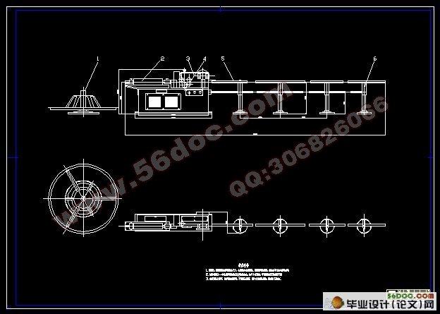
GT4-8�ֽ��ֱ��Ϊ�е�����ʽ����Ҫ�ɵ�ֱͲ�������䡢�жϻ��������ܼܡ�����������ɣ��ܹ���ֱ�ж�ֱ��Ϊ4—8�L�ĸֽ�ֽ��ǿ��650MPa���жϳ���Ϊ300-6000�L���жϳ������≤3��ǣ���ٶ�Ϊ40m/min����ֱͲת��Ϊ2800r/min�����ϡ�ǣ����ֱ��Ϊ90�L����ֱ��ǣ�����жϵ���ͺ�ΪJO2-42-4�ͣ���ֱ��ǣ�����жϹ���Ϊ5.5KW�����γߴ糤×��×��Ϊ7250�L×600�L×1220�L����������Ϊ1000Kg��
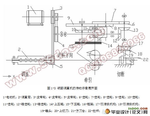
��ֱ���̣��ֽ����Ͳ�����ֱͲ����ֱͲ��װ���������ͬһ�������ϵĵ�ֱ�飬�ֽ���ÿ����ֱ����п��д��������ϡ���ǣ���ּн�����ǰ�ͽ��������жϻ��������ϲ��У���ֱͲ�Ը�����ת����ֱ�鷴�������������ֽ���ֽ��ֱ��ͬʱ����ֽ��������
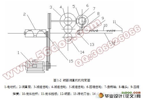
����ϵͳ���綯��ͨ�����ǽ�������װ�ô�����ֱͲ��ת�����е�ֱ���������綯���ϵ���һ�������Լ�һ�����ִ���ƫ���ᣬ�پ��������ּ��٣���������ѹ�����ٷ�����ת���Ӷ�ʵ�ָֽ�ǣ���˶����־���ƫ�����˫���������������ͷ�����˶��������е����봸ͷ����ʱ���ܵ���ͷ�û�����ɸֽ��жϡ�
�жϻ�����Ҫ�������֡����ˡ���ͷ���������ˡ���λ���ɡ���̨�������е������е������е�����ɡ�
������·��Ҫ���۶����������Ӵ������ȼ̵�����������ť���綯����ת�����ص���ɡ�
Ŀ ¼
ǰ �� 1
��һ�� �ֽ��ֱ������� 2
1.1 �ֽ��ֱ���ķ��� 2
1.2 �ֽ��ֱ�жϻ��Ĺ��켰���� 2
1.3 �ֽ��ֱ����ֱ����ԭ�� 3
1.4 �ֽ��ֱ������ԭ����������� 4
1.5 �ֽ��ֱ������Ҫ�������� 7
�ڶ��� ��Ҫ���� 8
2.1 �����ʺ��ʼ��� 8
2.1.1 �����ʼ��� 8
2.1.2 ���ʼ��㣬ѡ��綯�� 8
2.2 ��һ��Ƥ��������������� 12
2.2.1 ȷ����ƹ��� 12
2.2.2 ��ѡ�����ͺ� 12
2.2.3 ȷ�����ֵĻ�ֱ�� 12
2.2.4 ȷ�����ľ�ʹ��Ļ����� 13
2.2.5 ����С�ְ��� 13
2.2.6 ������ĸ��� 13
2.2.7 ��������������ϵ��غ� 14
2.3 �ڶ���Ƥ��������������� 14
2.3.1 ȷ����ƹ��� 14
2.3.2 ��ѡ�����ͺ� 15
2.3.3 ȷ�����ֵĻ�ֱ�� 15
2.3.4 ȷ�����ľ�ʹ��Ļ����� 15
2.3.5 ����С�ְ��� 16
2.3.6 ������ĸ��� 16
2.3.7 ��������������ϵ��غ� 16
2.3.8 ����������� 17
������ ֱ������� 18
3.1 ȷ�����ִ������ȵȼ� 18
3.1.2 ������Ӵ�ƣ��ǿ��ȷ�����ľ� 19
3.1.3 �������Ӵ�ƣ��ǿ�� 20
3.1.4 ����ݸ�����ƣ��ǿ�� 20
3.1.5 ������Ҫ�����ͼ��γߴ� 21
������ ������� 23
������ ��������ǿ��У�� 28
5.1 I��������ǿ��У�� 28
5.1.1 ��Ľṹ��� 28
5.1.2 ����������� 28
5.2 ����������ǿ��У�� 30
5.2.1 ��Ľṹ��� 30
5.2.2 ����������� 30
������ ��Ҫ����Ĺ�ӹ�Ҫ�� 34
6.1 ��ֱͲ����ֱ�� 34
6.2 ���� 34
6.3 ����ѹ����ѡ�ú͵��� 34
6.4 ��ֱ���ĸ����������װ������� 35
6.5 ����������ѡ������� 35
�� �� 36
�� л 37
����� 38
|
